Fig. 13
Download original image
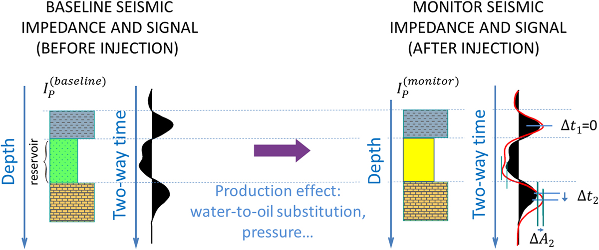
Principle of time-shift. Left: 3 layers with Ip values expressed in the depth domain induce the seismic signal expressed in the time domain. A fluid substitution is then performed inside the reservoir layer. Right: the horizons are at the same location in the depth domain than on the left, but Ip is different in the reservoir layer, leading to a slightly different seismic signal in the time-domain (time-shift Δt 2 and amplitude variation ΔA 2).