Table 2
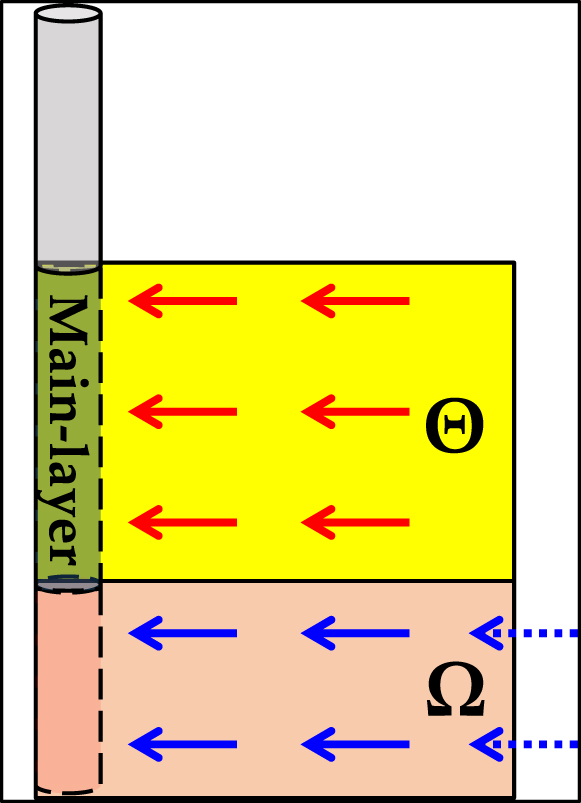
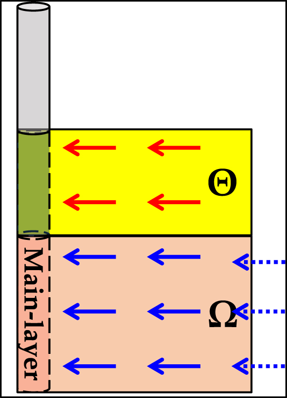
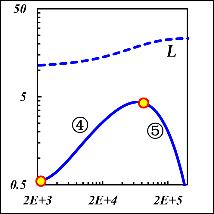
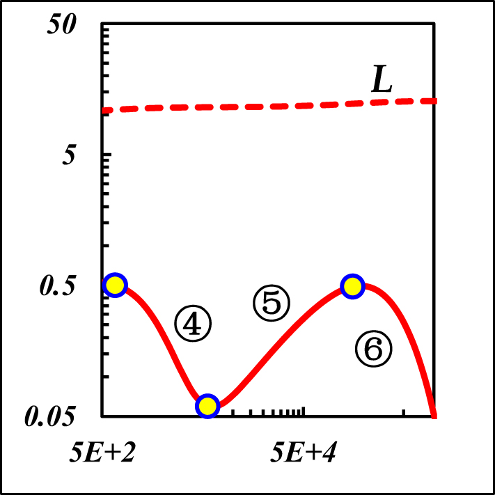
Boundary flow characteristics of Figure 4.
| Symbol description | Closed & const-pressure, r
eD
[Ω] = r
eD
[Θ] |
|
|---|---|---|
| κ[Θ] > κ[Ω] | κ[Ω] > κ[Θ] | |
| Model sketch |
|
|
| Identifiable window |
|
|
| Response behavior | ④Strong CBF: unit slope | ④Strong CpBF: const slope (−2.5 is its limit) |
| ⑤Weak CpBF: const pressure L = L 0/κ[Ω] | ⑤Weak CBF: unit slope | |
| ⑥Strong CpBF: const pressure L = L 0/κ[Ω] | ||
Where κ[Ω] is the permeability ratio of const-pressure layer, L 0 is the pressure value when the κ[Ω] = 1.
Notes: “CBF” is Closed Boundary Flow and “CpBF” is the Const-Pressure Boundary Flow. “Strong” indicates the boundary layer is the main-flow layer, and “Weak” indicates the boundary layer is the non-main-flow layer.