Regular Article
Research on kinematics analysis of spherical single-cone PDC compound bit and rock breaking simulation verification
1
School of Mechanical Engineering, Xihua University, Chengdu, Sichuan 610039, PR China
2
School of Mechatronic Engineering, Southwest Petroleum University, Chengdu, Sichuan 610500, PR China
* Corresponding author: This email address is being protected from spambots. You need JavaScript enabled to view it.
Received:
16
April
2021
Accepted:
2
June
2021
Abstract
The single-cone bit has become the first choice for slim hole sidetracking and deep well drilling with its unique rock breaking method and high ROP (Rate Of Penetration), with its main failure mode being of early excessive wear of the cutting teeth. In order to improve the adaptability of single-cone bits to hard and highly abrasive formations, a spherical single-cone Polycrystalline Diamond Compact (PDC) compound bit is designed. According to the characteristics of the tooth profile, the way of tooth arrangement and the way of contact between the cutting teeth and the rock, the acceleration equation to the cutting teeth of the spherical single-cone PDC compound bit is established. The acceleration of the single-cone bit is verified by numerical simulation experiment of rock-breaking. The shaft inclination angle of the cone, the position and height of the PDC teeth, the radius of the PDC teeth, the lateral rotation angle and the front inclination angle on the acceleration are studied. The results show that as the shaft inclination angle increases, the bit transmission ratio gradually increases, and the harder the rock formation, the larger the transmission ratio of the single-cone bit; the shaft inclination angle and the position of the PDC tooth have a greater influence on the acceleration of the PDC tooth, and the radius, lateral rotation angle and front inclination angle of the PDC tooth have a small influence on the acceleration of the PDC tooth; rock properties have an impact on the acceleration of the cutting teeth, with the acceleration of the cutting teeth in hard rock formations being higher than that in soft rock formations; near the top of the cone, the absolute acceleration of the cutting teeth will fluctuate sharply and cause severe wear of the cutting teeth, so the tooth distribution in this area should be strengthened; on the premise that the bearing life of the single-cone bit is allowed, the value of the shaft inclination angle β can be approached to 70°. The relative error between the theoretical analysis results of the acceleration of the PDC cutter and the rock-breaking simulation experiment results is between −0.95% and −2.24%. This research lays a theoretical foundation for the dynamic research of spherical single-cone PDC compound bit.
© C. Kong et al., published by IFP Energies nouvelles, 2021
 This is an Open Access article distributed under the terms of the Creative Commons Attribution License (https://creativecommons.org/licenses/by/4.0), which permits unrestricted use, distribution, and reproduction in any medium, provided the original work is properly cited.
Nomenclature
ρ : Radius vector, as shown in Figure 6, mm;
θ : Polar angle, degree;
Z : Vertical height, mm;
L : Distance from the center of the cone to the back cone plane of the cone, mm;
h C : Position height of the center point C of the PDC cutting tooth surface, mm;
r C : Radius of the characteristic circle where point C is located, mm;
α : Rotation angle of the cone relative to the cone shaft, degree;
α 0 : Initial rotation angle of the cone relative to the cone shaft, degree;
x1, y1, z1: Coordinate value of point Q in the coordinate system O1X1Y1Z1, mm;
r Q : Radius of PDC cutter, mm;
β : Shaft inclination angle of single-cone bit, degree;
θ : Position angle of the drill bit within 0 ~ t, the position change caused by the rotation of the drill bit, degree;
θ 0 : Extreme position angle of the origin O′ of the moving coordinate system, degree;
Z O′ : Vertical height of the moving coordinate origin O′, mm;
δ : Front inclination angle of PDC cutter, degree;
η : Lateral rotation angle of PDC cutter, degree;
γ : Angle between the baseline of the PDC tooth and the axis of the drill bit, degree;
σ 0 : Uniaxial compressive strength of limestone, and σ0 = 124 MPa;
σ : Uniaxial compressive strength of any rock, MPa.
1 Introduction
The main drill bits currently used in drilling engineering are PDC bits and tri-cone bits. The single-cone bit is a cutting type drill bit between the tri-cone bit and the Polycrystalline Diamond Compact (PDC) bit [1], and the cutting teeth on the cone crush the rock by rolling, scraping, and twisting. With its unique rock-breaking method and high ROP (Rate Of Penetration), it has won the favor of the drilling industry and has become the preferred drill bit for slim hole sidetracking and deep well drilling [2–6]. Although the single-cone bit is a good choice for slim hole drilling because of its good formation adaptability, strong guiding ability and easy to be small-sized [1, 7], according to the field application tracking investigation and statistical analysis, the single-cone bit also has a fatal weakness, that is, the wear resistance of the cutters is seriously insufficient [1, 8, 9]. The spherical single-cone bits currently used in the oil field (Fig. 1) all use cemented carbide inserts (such as cone button teeth, wedge teeth, etc.), which can only be used in soft formations; For hard formations with high abrasiveness, the early wear is severe and the life span is short [10, 11]. This is because the single-cone bit will produce relatively large slip at the bottom of the well when it is working (Fig. 2), resulting in severe wear of the carbide cutting teeth. Therefore, the wear resistance of the cutting teeth will directly determine the working life of the single-cone bit. Once the cutters are dull, the drilling speed will decrease sharply. The main reason why the single-cone bit is less and less used is that the teeth are not wear-resistant, which leads to the ROP decline and short service life of the bit. It is of great practical significance and development prospect to research and design single-cone bits with strong abrasion resistance and wider lithological adaptability [12, 13].
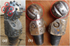 |
Fig. 1 Failed single-cone bit (a) worn cutting teeth (b) broken cutting teeth. |
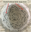 |
Fig. 2 Bottom hole pattern of single-cone bit. |
Ma [14] founded the geometry and kinematics of modern roller cone bits. Wang et al. [15] and others [16] designed a special-shaped single-cone bit to increase the working life of the bit, but the special-shaped single-cone bit is not a full-hole drill, and the rock-breaking efficiency is still not high. Li [17] researched and designed a new type of impact press-in single-cone bit. After field application, it was found that the bit was worn seriously. Yu and Ding [18], Yu [19] and Deng et al. [20] studied the geometry, kinematics, and dynamics of the spherical single-cone bit, and discussed the design method of the tooth surface structure of the single-cone bit. Yu et al. [7] studied the influence of different geometric parameters and motion parameters for spherical single-cone bits on rock-breaking. However, many single-cone bit researchers have not conducted in-depth and detailed studies on the acceleration of PDC cutting teeth for the special motion trajectory of single-cone bits.
In recent years, researchers have done a lot of research on bit technology. New bit technology is emerging, especially the improvement of bit performance brought by new bit structures. Baker Hughes Company has developed a new hybrid bit product by combining fixed PDC and unfixed cone. The special structure enables the bit to achieve good drilling results in some special formations and drilling requirements [21–25]. Smith bits of Schlumberger has successively launched 360° rotary PDC bit [26, 27] and conical diamond element Bits [28–30]. These two kinds of bit have good performance in some special difficult to drill formation. Chen et al. proposed a new technology of single-cone bit, which is composed of fixed and unfixed [31]. The research team led by Professor Yang of Southwest Petroleum University proposed a diamond bit with unfixed cutting structure through structural innovation [32, 33], and many useful research results have been obtained [34–36]. Compared with the existing cone bit and PDC bit, the new bit has obvious advantages in rock breaking efficiency and service life. The bit is expected to form an efficient rock breaking tool in the near future. The structure of the bit has a decisive influence on the adaptability and performance of the bit. With the structural innovation, new research on new drill bits and new tools will have new breakthroughs [37]. Sometimes, the new bit structure can play a role of surprise and drive the development of drilling technology.
In order to overcome the shortcomings of the prior art (Fig. 1), improve the wear resistance of the single-cone bit and prolong the service life of the bit, based on an in-depth analysis of the structural characteristics and working principles of the single-cone bit, this paper adopts the design concept of the spherical single-cone bit + PDC bit and the principle that the PDC cutting teeth work slowly and alternately on the cone, with the design concept of spherical single-cone PDC compound bit proposed (Fig. 3). In order to make this new type of bit better serve the needs of oil drilling production, we need to conduct an in-depth study on the kinematics and related parameters for the PDC teeth on the single-cone bit. However, due to the changes in the tooth profile characteristics and tooth arrangement method for the new drill bit, the characteristic points on the PDC cutting tooth edge can no longer be simplified to any point on the cone sphere. Moreover, PDC teeth have cutting angles such as front inclination angle and lateral rotation angles during the rock-breaking process. It is necessary to re-establish the kinematics equations of the cutting teeth of the spherical single-cone PDC compound bit to thoroughly grasp the acceleration characteristics of the new type of bit, which provides basic support and reference for the dynamic research, subsequent design, development and application of this kind of bit.
 |
Fig. 3 Spherical single-cone PDC compound bit. |
2 Establishment coordinate system
As shown in Figure 4, when the spherical single-cone PDC compound bit is working, the movement of the cone includes the revolution of the bit body and cone around the center line of the bit, the movement along the direction of the center line of the bit, and the rotation of the cone around the cone axis. Any studies on the basic motions of cutters on cone shall be based on deep understanding of the features of bit in the coordinate system, basic plane and structure.
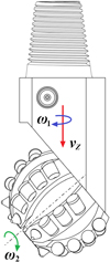 |
Fig. 4 The motion of spherical single-cone PDC compound bit. |
2.1 Static cylindrical coordinate system
Use the central axis of a single-cone bit as the coordinate axis OZ to establish a static/fixed cylindrical coordinate system (static coordinate system) [20], set the polar axis on a horizontal reference plane and in a certain direction. Thereafter, a point Q within the space can be represented by Q (ρ, θ, Z), as shown in Figure 5.
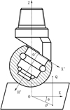 |
Fig. 5 Cylindrical coordinate system for bit. |
2.2 Dynamic cylindrical coordinate system
Set up a dynamic cylindrical coordinate system for a single-cone [19], with the origin O′ set at the bottom center point of cone, the vertical axis O′H′ coinciding with the axis of cone, and polar axes O′X′ and O′H′ perpendicular with each other. The plane defined by H′O′X′ is called as a polar axis plane of cone.
Figure 6 shows the projection relationships of a complex cylindrical coordinate system, including: (a) view from direction A for the back cone plane of cone; (b) front view of single-cone; and (c) top view in addition to (b). Figure 6 indicates the parameters for bit structure as (L, R, β), parameters for bit and cone positions as (θ0, ZO′, α0), parameters for PDC cutter’s position on cone as (hC, rC, γ, δ, η), and parameters of point Q’s position on PDC cutter blade profile as (rQ, φ).
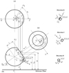 |
Fig. 6 Geometry of spherical single-cone PDC compound bit. |
Set up four rectangular coordinate systems for PDC cutters and respectively from the center points of four cutters [38]. Set up a coordinate system O1X1Y1Z1 for the position of PDC cutters, to make O1Z1//OZ and pointing to the same direction as OZ, and O1X1 in a horizontal direction and perpendicular to OZ. Rotate O1X1Y1Z1 around O1Y1 by an angle γ (the included angle between the reference line of cutter and the axis of bit) in the clockwise direction to obtain a coordinate system O1X2Y2Z2, to make O1X2 collinear with the reference line of cutter and pointing to the external of bit. Rotate O1X2Y2Z2 around O1X2 by η in the clockwise direction to obtain a coordinate system O1X3Y3Z3, to make O1X3 collinear with the reference line of cutter and pointing to the direction against from the center line of bit (coinciding with O1X3). Rotate O1X3Y3Z3 around O1Z3 by δ in the counterclockwise direction to obtain a coordinate system O1X4Y4Z4, to make O1Z4 perpendicular to the directional reference line of PDC cutter (coinciding with O1Z3).
In consideration of expressing all geometrical features of a cutter, such as points, lines and planes, define the parameter equations for the blade curves of the cutter as follows:
 (1)
(1)
According to the principles for transformation of rectangular coordinate system, obtain the equations for the position coordinates for the blade profile of PDC cutter as follows:
 (2)
(2)
3 Geometrical equations for describing motion of PDC cutters
During operation, the motion of a single-cone bit consists of rotation and displacement, which are for the convenience of study analyzed in separation before combination of them.
3.1 Rotation of cone
3.1.1 Relative rotation of cone around cone shaft
Assume that the bit does not rotate, and the cone rotates around the cone shaft. Define the center point on a surface of PDC cutter as the characteristic point C (ρ, θ, Z) and the initial position as α0. After a time lapse t, point C moves to point C′ and arrives at a position angle α0 + α. Each view in Figure 6 includes the point C′ and its projection.
The true length is indicated as the distance between O and C′ to represent the radius vector of point C′ in the top view. OC′ constitutes the oblique side of the right triangle ON′C′, of which the right angle sides ON′ and N′C′ are as follows:
 (3)
(3)
 (4)
(4)
wherein:
 (5)
(5)
Subject to the time lapse t, calculate the radius vector ρQ of a point Q on the blade profile of cutter can be expressed as:
![Mathematical equation: $$ {\rho }_{\mathrm{Q}}=\sqrt{{\left[\left(L-{h}_{\mathrm{C}}\right)\mathrm{cos}\beta +{r}_{\mathrm{C}}\mathrm{cos}\left({\alpha }_0+\alpha \right)\mathrm{sin}\beta +{x}_1\right]}^2+{\left[{r}_{\mathrm{C}}\mathrm{sin}\left({\alpha }_0+\alpha \right)+{y}_1\right]}^2}. $$](/articles/ogst/full_html/2021/01/ogst210105/ogst210105-eq6.gif) (6)
(6)
3.1.2 Rotation of cone and cone shaft around the center axis of bit
Under the assumption that only the bit rotates, and the cone doesn’t rotate around the cone shaft, point C′ conducts fixed-axis rotation around the center axis of bit, and, after the time lapse t, point C′ moves to point C′′ after travelling over the angle θ, as shown in Figure 6. The true value is reflected in the top view for the polar angle θC″ of the characteristic point C″, and θC′′ is the sum of the polar angle of point O′ and ∠N′OC″, wherein:
 (7)
(7)
 (8)
(8)
Accordingly, subject to the time lapse t, calculate the polar angle θQ of a point Q on the blade profile of cutter can be expressed as:
 (9)
(9)
3.2 Displacement of cone
During operation, the cone moves along the center axis of bit in addition to rotation. The true length is reflected in Figure 6b for the net vertical height ZC′ of the characteristic point C after the time t. Accordingly, subject to the time lapse t, calculate the vertical height ZQ of a point Q on the blade profile of cutter can be expressed as:
 (10)
(10)
Equations (6), (9) and (10) are kinematic geometric equations of the spherical single-cone PDC compound bit.
4 Acceleration equation of PDC tooth on single-cone
In order to facilitate the study of the acceleration of the PDC teeth on the cone, the rotation and movement of the cone are studied separately and combined.
The angular velocity of the bit body is ω1, and the angular acceleration is ε1.
 (11)
(11)
The angular velocity of the cone around the cone axis is ω2, and its angular acceleration is ε2.
 (12)
(12)
The up and down position of the bit body is ZO′, and the acceleration is aZ
 (13)
(13)
ε1, ε2 and aZ are all random variables, and through experimental measurements, it can be seen how their instantaneous real values change with time.
The acceleration of a characteristic point on a single-cone PDC tooth, especially the acceleration when the cutting tooth impacts with the bottom of the hole, is an important parameter for rock-breaking and cutting tooth strength. However, the actual measurement of the acceleration and dynamic load of the cutting teeth is very troublesome and cannot be implemented on a large scale. It is obviously very useful if the mathematical relationship between the acceleration of the PDC teeth of the single-cone bit and the above-mentioned measurable bit acceleration ε1, ε2 and aZ can be established.
In order to facilitate the study of the acceleration of the single-cone bit of the PDC tooth, the absolute movement of a certain characteristic point on the single-cone PDC tooth is regarded as the combination of the following three kinds of movements. That is, for the longitudinal implicated motion of point Q, its position variable is ZQ, and its acceleration is  ; for the tangentially implicated movement of point Q, its position variable is the polar angle θQ, and the acceleration is aQτ; for the radial relative movement of point Q, the position variable is the vector radius ρQ, and the acceleration is aQρ; the three moving directions are 90° with each other. Starting from the geometrical equation of motion of the single-cone bit, the acceleration equation of any point on the PDC tooth is established.
(1) Relative acceleration a r
The acceleration caused by the radial movement is the relative acceleration, with the relative acceleration being the derivative of the radial velocity with respect to time t.
Let
 (14)
(14)
 (15)
(15)
 (16)
(16)
 (17)
(17)
 (18)
(18)
![Mathematical equation: $$ {\lambda }_{{\mathrm{C}}_{\rho }}=\frac{1}{{\rho }_{\mathrm{Q}}}\left[\begin{array}{c}\mathrm{cos}\left({\alpha }_0+\alpha \right)(\mathrm{cos}\phi \mathrm{sin}\mathrm{\delta }\mathrm{cos}\mathrm{\eta }+\mathrm{sin}\mathrm{\phi }\mathrm{sin}\mathrm{\eta })\\ -\mathrm{sin}\beta \mathrm{sin}\left({\alpha }_0+\alpha \right)(\mathrm{cos}\phi \mathrm{cos}\mathrm{\delta }\mathrm{sin}\mathrm{\gamma }+\mathrm{cos}\phi \mathrm{sin}\mathrm{\phi }\mathrm{sin}\mathrm{\eta }\mathrm{cos}\gamma -\mathrm{sin}\phi \mathrm{cos}\eta \mathrm{cos}\gamma )\end{array}\right]. $$](/articles/ogst/full_html/2021/01/ogst210105/ogst210105-eq21.gif) (19)
(19)
Then there is
![Mathematical equation: $$ \begin{array}{c}{a}_r=\frac{{\mathrm{d}}^2{\rho }_{\mathrm{Q}}}{{\mathrm{d}t}^2}=\frac{1}{{\rho }_{\mathrm{Q}}}\left[({r}_{\mathrm{C}}^2-{B}^2)\mathrm{cos}2\left({\alpha }_0+\alpha \right)-B\mathrm{cos}\left({\alpha }_0+\alpha \right)\left(A+\mathrm{C}\right)\right]-D{r}_{\mathrm{C}}\mathrm{sin}({\mathrm{\alpha }}_0+\mathrm{\alpha })]{\omega }_2^2\\ +\frac{1}{{\rho }_{\mathrm{Q}}}\{\left[{r}_{\mathrm{C}}-{\mathrm{cos}}^2\mathrm{\beta }\mathrm{sin}\left({\mathrm{\alpha }}_0+\mathrm{\alpha }\right)+D\right]{r}_{\mathrm{C}}\mathrm{cos}({\mathrm{\alpha }}_0+\mathrm{\alpha })]\left(A+C\right)\}{\epsilon }_2\\ -\frac{1}{{\rho }_{\mathrm{Q}}}{\left({\lambda }_{{\mathrm{C}}_{\mathrm{\rho }}}+{\lambda }_{{\mathrm{Q}}_{\mathrm{\rho }}}{r}_Q\right)}^2{r}_{\mathrm{C}}^2{\omega }_2^2,\end{array} $$](/articles/ogst/full_html/2021/01/ogst210105/ogst210105-eq22.gif) (20)
(20)
(2) Tangentially implicated acceleration a eτ
Let
![Mathematical equation: $$ m=\frac{A\enspace \mathrm{cos}\left({\alpha }_0+\alpha \right)+B+C\mathrm{cos}\left({\alpha }_0+\alpha \right)+D\mathrm{sin}\beta \mathrm{sin}\left({\alpha }_0+\alpha \right)}{{\left[A+B\mathrm{cos}\left({\alpha }_0+\alpha \right)+C\right]}^2+{\left[{r}_{\mathrm{C}}\mathrm{sin}\left({\alpha }_0+\alpha \right)+D\right]}^2}, $$](/articles/ogst/full_html/2021/01/ogst210105/ogst210105-eq23.gif) (21)
(21)
![Mathematical equation: $$ \frac{\mathrm{d}m}{\mathrm{d}\alpha }=\frac{D\mathrm{sin}\beta \mathrm{cos}\left({\alpha }_0+\alpha \right)-\mathrm{sin}\mathrm{cos}\left({\alpha }_0+\alpha \right)(A+C)}{{\rho }_{\mathrm{Q}}^2}\left[\left(A+C\right)\mathrm{cos}\left({\alpha }_0+\alpha \right)+B+D\mathrm{sin}\beta \mathrm{sin}\left({\alpha }_0+\alpha \right)\right]\times \frac{2\left\{\left[A+B\mathrm{cos}\left({\alpha }_0+\alpha \right)+C\right]{r}_{\mathrm{C}}\mathrm{sin}\beta \mathrm{sin}\left({\alpha }_0+\alpha \right)-\left[{r}_{\mathrm{C}}\mathrm{sin}\left({\alpha }_0+\alpha \right)+D\right]{r}_{\mathrm{C}}\mathrm{cos}\left({\alpha }_0+\alpha \right)\right\}}{{\rho }_{\mathrm{Q}}^4}. $$](/articles/ogst/full_html/2021/01/ogst210105/ogst210105-eq24.gif) (22)
(22)
Then there is
 (23)
(23)
(3) Implicated centripetal acceleration a eρ
The radially implicated centripetal acceleration caused by the rotation of the drill bit is:
 (24)
(24)
(4) Longitudinal implicated acceleration a eZ
 (25)
(25)
(5) Coriolis acceleration a k
The Coriolis acceleration caused by the change in the direction of the relative speed caused by the implicated rotation and the change in the magnitude of the implicated speed caused by the relative speed, expressed by the vector ak. By the definition of Coriolis acceleration, its magnitude is:
 (26)
(26)
wherein, Ψ is the angle between the relative speed and the angular velocity of the implicated rotation, Ψ = 90°; the direction of ak is perpendicular to the plane defined by ωQ and vQρ, pointing to the tangential direction.
Thus, the radial acceleration aQρ, the tangential acceleration aQτ, and the longitudinal acceleration aQZ at point Q on the cutting tooth are obtained:
the radial acceleration a Qρ
![Mathematical equation: $$ \begin{array}{c}{a}_{\mathrm{Q}\rho }={a}_r+{a}_{{e\rho }}=\frac{1}{{\rho }_{\mathrm{Q}}}\left[{(r}_{\mathrm{C}}^2-{B}^2\right)\mathrm{cos}2\left({\alpha }_0+\alpha \right)-B\mathrm{cos}\left({\alpha }_0+\alpha \right)\left(A+C\right)-D{r}_{\mathrm{C}}\mathrm{sin}\left({\alpha }_0+\alpha \right)]{\omega }_2^2\\ +\frac{1}{{\rho }_{\mathrm{Q}}}\left\{\left[{r}_{\mathrm{C}}{\mathrm{cos}}^2\beta \mathrm{sin}\left({\alpha }_0+\alpha \right)+D\right]{r}_{\mathrm{C}}\mathrm{cos}\left({\alpha }_0+\alpha \right)-B\mathrm{sin}\left({\alpha }_0+\alpha \right)\left(A+C\right)\right\}{\epsilon }_2\\ -\frac{1}{{\rho }_{\mathrm{Q}}}{\left({\lambda }_{\mathrm{C}\rho }+{\lambda }_{\mathrm{Q}\rho }{r}_{\mathrm{Q}}\right)}^2{r}_{\mathrm{C}}^2{\omega }_2^2+{\rho }_{\mathrm{Q}}{\left({\omega }_1-m{r}_{\mathrm{C}}{\omega }_2\right)}^2\end{array}, $$](/articles/ogst/full_html/2021/01/ogst210105/ogst210105-eq29.gif) (27)
(27)
the tangential acceleration a Qτ
 (28)
(28)
the longitudinal acceleration aQZ
 (29)
(29)
so, the absolute acceleration aQ at point Q on the cutting tooth is:
 (30)
(30)
5 Calculation examples and analysis
5.1 Relationship between the transmission ratio of the single-cone bit and the rock
The relationship between the roller speed and the bit rotation speed is the transmission ratio. Through analyzing and summarizing the experimental data of the transmission ratio of the spherical single-cone bit in the literature [39], the empirical formula of the transmission ratio i can be obtained.
 (31)
(31)
Three common rocks are selected: sandstone (σ = 33.44 MPa), limestone (σ = 124 MPa) and granite (σ = 236 MPa). According to the empirical formula of transmission ratio, the change trend of transmission ratio i of single-cone bit in three kinds of rocks with shaft inclination angle β can be obtained, as shown in Figure 7. It can be seen from the curve in the figure that as β increases, the bit transmission ratio i also gradually increases, and that the transmission ratio of a single-cone bit in granite is higher than that in sandstone, that is, the harder the rock, the higher the transmission ratio of the bit. Of course, the transmission ratio of a single-cone bit is not only related to the shaft inclination angle and rock characteristics, but also to the bit tooth surface structure. However, according to previous experimental studies, it can be known that the shaft inclination angle and rock characteristics are the main factors affecting the transmission ratio, so the empirical formula for transmission ratio has certain applicability to single-cone bits. The influence of the new tooth surface structure on the transmission ratio of the spherical single-cone PDC compound bit needs to be supplemented and improved in the follow-up experimental research.
 |
Fig. 7 Change of transmission ratio at shaft inclination angle. |
5.2 Analysis of factors affecting acceleration
In order to further clarify the influence of each parameter of the PDC tooth single-cone bit on the acceleration, the acceleration of the PDC tooth single-cone bit is quantitatively analyzed and studied in combination with some parameters given in reference [20], with the given parameters being L = 30 mm, R = 50 mm, hC = 40 mm, β = 60°, α = 30°, η = 5°, δ = 38°, rQ = 6.72 mm, ω1 = 60 r/min, and i = 0.748 (limestone). The diameter of the spherical single-cone PDC compound bit is 118 mm. The front inclination angle δ, the radius rQ of the PDC tooth, the lateral rotation angle η, the shaft inclination angle β, the position height hC of the PDC tooth, and the rock strength are selected as independent variables. The above basic parameters are substituted into equations (27)–(30) for numerical calculation.
The acceleration simulation calculation result of the spherical single-cone PDC compound bit is shown in Figures 8–12. It can be seen from Figure 8 that the tangential acceleration aQτ and the absolute acceleration aQ increase with the increase of the front inclination angle δ, and that the radial acceleration aQρ decreases slightly with the increase of δ; the longitudinal acceleration aQZ has nothing to do with δ. It can be seen from Figure 9 that aQρ, aQτ and aQ all increase slightly with the increase of the radius rQ of the PDC tooth, but the amplitude of the change is small; aQZ has nothing to do with rQ. It can be seen from Figure 10 that aQρ, aQτ and aQ all decrease slowly with the increase of the lateral rotation angle η; aQZ has nothing to do with η. It can be seen from Figure 11 that the shaft inclination angle β has a relatively large impact on acceleration, where aQρ decreases as β increases, and that both aQτ and aQZ first increase and then decrease with β increase; as β increases, aQ first decreases, then remains unchanged, and finally decreases. It can be seen from Figure 12 that the position height hC of the PDC tooth also has a relatively large impact on the acceleration, and between 0 and 65 mm, aQρ, aQτ and aQ all increase as hC increases; between 65 and 80 mm, aQτ decreases sharply with the increase of hC and approaches zero, aQρ and aQ increase greatly with the increase of hC, and decrease sharply when they are close to the top of the cone; aQZ has nothing to do with hC.
 |
Fig. 8 Effect of front inclination angle on acceleration. |
 |
Fig. 9 Effect of PDC cutter radius on acceleration. |
 |
Fig. 10 Effect of lateral rotation angle on acceleration. |
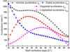 |
Fig. 11 Effect of shaft inclination angle on acceleration. |
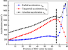 |
Fig. 12 Effect of PDC cutter position on acceleration. |
Sandstone (σ = 33.44 MPa), limestone (σ = 124 MPa) and granite (σ = 236 MPa), and combine equation (31) are selected to quantitatively analyze and calculate the absolute acceleration of the PDC teeth of the single-cone bit, with the results shown in Figures 13–15. The analysis results show that because rock formations of different hardness will cause changes in the bit transmission ratio, the rock formations also have a certain influence on the acceleration of the cutting teeth, and that the acceleration of the cutting teeth in sandstone is slightly lower than that in granite; the absolute acceleration of the cutting teeth at most positions on the cone in different rock formations tends to be gentle with the increase of β. However, near the top of the cone, the absolute acceleration of the cutting teeth will fluctuate violently and cause severe wear of the cutting teeth; the greater β, the closer the absolute acceleration fluctuation position is to the top of the cone, and the smaller the fluctuation amplitude. Therefore, the tooth placement in the area to the right of the dotted line in Figures 13–15 require special attention from single-cone bit researchers. At the same time, the larger β, the smaller the absolute acceleration, indicating that the inertial force of the drill bit is smaller and that it is more beneficial to the strength of the PDC tooth; however, considering the wear of the roller bearing [40, 41], the shaft inclination angle β of the single-cone bit cannot be designed too large.
 |
Fig. 13 Relationship between the absolute acceleration and hC (sandstone). |
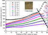 |
Fig. 14 Relationship between the absolute acceleration and hC (limestone). |
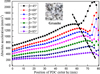 |
Fig. 15 Relationship between the absolute acceleration and hC (granite). |
The bit design should try to achieve the goal of equal life, that is, the life of each component of the cone bit is almost the same. For a single-cone bit, it mainly means that the roller bearing and the bit cutting teeth reach the same life. Therefore, under the premise that the bearing life of the single-cone bit is allowed, the shaft inclination angle β can be approached to 70°.
5.3 Multi-factor composite analysis of acceleration
According to Figures 13–15, it is known that among the various factors affecting the acceleration of the cutting teeth of the spherical single-cone PDC compound bit, the shaft inclination angle and the position height of the PDC teeth have the greatest impact on the acceleration. Therefore, in order to comprehensively investigate the influence trend of β and hC of the PDC tooth on the acceleration, β and hC are used as independent variables at the same time in analyzing and calculating the radial acceleration aQρ, tangential acceleration aQτ, longitudinal acceleration aQZ and absolute acceleration aQ in the limestone with these two independent variables, as shown in Figures 16–19.
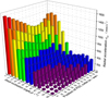 |
Fig. 16 Change of radial acceleration along with hC and β. |
 |
Fig. 17 Change of tangential acceleration along with hC and β. |
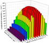 |
Fig. 18 Change of longitudinal acceleration along with hC and β. |
 |
Fig. 19 Change of absolute acceleration along with hC and β. |
It can be seen from Figures 16–19 that when the position height hC of the PDC teeth and the shaft inclination angle β increase at the same time, the radial acceleration aQρ first decreases and then tends to be gentle. When β = 40°~60°, the radial acceleration aQρ change law tends to be stable as a whole, and slowly increases with the increase of hC. The tangential acceleration aQτ first increases and then slowly decreases with the increase of β and hC. When β = 30°~40°, the tangential acceleration aQτ reaches the maximum value, and the maximum value is close to the top area of the cone. The longitudinal acceleration aQZ first increases and then decreases with the increase of β and hC. When β = 40°, the longitudinal acceleration aQZ of the PDC teeth in the middle of the cone reaches the maximum. The absolute acceleration aQ decreases first and then stabilizes with the increase of β and hC. When β and hC take the minimum at the same time, the absolute acceleration aQ reaches the maximum; when β takes the maximum, the absolute acceleration aQ of the PDC tooth at the end of the cone reaches the minimum.
In order to verify the theoretical analysis results of the acceleration of the spherical single-cone PDC compound bit in this paper, the nonlinear dynamical model is established to simulate the dynamic rock breaking process of the spherical single-cone PDC compound bit on basis of which the acceleration state of the bit element during the rock breaking process is simulated. It provides a theoretical basis for the application and design of the spherical single-cone PDC compound bit.
6 Rock-breaking simulation experiment
In the actual drilling process, there are many factors that affect the rock-breaking of the drill bit. In the process of numerical simulation of the rock-breaking of the drill bit using the finite element method, it is impossible to consider the influence of all factors on the simulation results. The specific problems and research goals should be addressed. The simulation model is appropriately simplified and necessary assumptions are made. To facilitate the analysis the drilling process of the spherical single-cone PDC compound bit, the following assumptions are taken:
The palm and cone of the drill bit are regarded as rigid bodies.
-
The influences of temperature, confining pressure, and drilling fluid are neglected.
The bottom of the well is kept clean at all times, that is, the rock grid unit will be automatically deleted after failure, ignoring its impact on the subsequent cutting.
The rock is continuous isotropic medium, ignoring the effects of initial cracks and internal pressure.
The axis of the drill bit coincides with the axis of the borehole, ignoring the possible radial displacement of the drill bit.
6.1 Finite-Element model of the drill bit-rock system
The PDC bit exhibits highly nonlinear characteristics during the rock-breaking process, including geometric nonlinearity, material nonlinearity and contact nonlinearity. By adopting the finite element method, treat the spatial domain of the cutter-rock contacting system at time t as Ω, and the body force, boundary stress and Cauchy’s stress respectively as b, r, rC and σC, then the contacting issue could be represented as [42, 43]:
 (32)
(32)
wherein, Γf is the border for a given boundary force, Γc is the contact boundary, δu is the virtual displacement, δe is the virtual strain, ρ is the density, a1 represents the acceleration. By discretizing the spatial domain Ω with finite element method, one can obtain the following equation:
 (33)
(33)
wherein, M is the mass matrix, ϋ is the acceleration vector, t is the time variable, p is the external force vector, c is the contact force and friction force vector, h is the internal stress vector, u is the object displacement, ξ is the variable associated with contact surface characteristics, and λ represents the variable associated with constitutive relation of materials.
Considering that a proper plastic constitutive model is the key of accurately simulating the yielding, hardening and damaging process, and that bottom-hole rock is a kind of granular material so that the rock element will be expanded when suffering shear force, Drucker-Prager model [36, 44] is adopted in this paper.
According to the above theory, combined with the bit structure designed in Figure 3, with the given structural parameters being L = 30 mm, R = 50 mm, β = 70°, η = 5°, δ = 38°, rQ = 6.72 mm, the nonlinear dynamic finite element model of drill bit-rock system was established in ABAQUS program, as shown in Figure 20a. According to the Saint-Venant principle, the size of the rock is 220 mm in diameter and 100 mm in height. To reduce the time of bottom hole formation and make all the cutter interact with the rock earlier, a pre-contact bottom hole is set on the surface of the rock model according to the size of the spherical single-cone bit, as shown in Figure 20b. The 8-node reduced integration element C3D8R with high accuracy, robustness and hourglass control was employed to discrete the rock model, and the rock’s area nearby the cutter was finely meshed, the grid size is about 2 mm. The rock-breaking simulation model was totally divided into 912 396 elements. And the system of unit (mm-N-s) was applied in the numerical model, while for convenience, results were displayed according to the engineering conventions. The mechanical parameters of the material of the drill bit are listed in Table 1. The mechanical parameters of rock material are listed in Table 2.
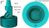 |
Fig. 20 Finite element model of the drill bit-rock system (a) Overall model, (b) Rock model. |
Mechanical parameters of each part of the drill bit.
As shown in Figure 21, the overall coordinate system of the spherical single-cone PDC compound bit is in the same direction as the global coordinate system. The z-axis of the single-cone bit coincides with the rock center axis, and the positive direction of the z-axis is the longitudinal movement direction of the single-cone bit, the x-axis is horizontal and perpendicular to the z-axis, that is, the x-o-z plane is parallel to the surface of the rock model.
 |
Fig. 21 Boundary setting of rock-breaking simulation. |
The rock-breaking simulation adopts ABAQUS/Explicit analysis method. Non-reflecting boundary and fixed constraint were applied to the rock surfaces except the top one. The contact type between the cutter and rock was eroding surface to surface. Considering the friction between the cutting surface and rock, the friction coefficient of contact surfaces was set to 0.4 [45]. The simulation loading process is divided into two steps: In the first step, the Weight On Bit (WOB) is 100 kg, which is applied to the upper surface of the bit leg to keep the cutter in contact with the rock. In the second step, the WOB is 2000 kg, which is applied to the upper surface of the bit leg (Fig. 21); at the same time, the rotation speed applied to the center axis of the bit is 60 r/min, so that the single-cone bit rotates at a uniform speed around the center axis of the rock model. Set the simulation time to 6 seconds. The single-cone bit designed in Figure 3 has 25 PDC cutters distributed. Due to the large number of cutting teeth, according to the distribution of PDC cutter on the surface of the cone, seven representative PDC cutters are selected for research, and their distribution positions on the cone are shown in Figure 22. The position height hC of the seven PDC cutters are shown in Table 3.
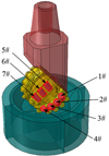 |
Fig. 22 Number of cutters. |
Position parameters of PDC cutter.
6.2 Results and discussion
The equivalent plastic strain cloud diagram of the rock in the simulation of rock-breaking with a spherical single-cone PDC compound bit within 1–6 s is shown in Figure 23. It can be seen from Figure 23 that as the working time of the spherical single-cone PDC compound bit increases, a complete spherical bottom hole is gradually formed in the center of the rock model.
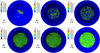 |
Fig. 23 Equivalent plastic strain in rock-breaking process. |
During the rock-breaking process, the overall longitudinal velocity and acceleration of the drill bit (in the direction of the borehole axis) vary with the drilling time as shown in Figures 24 and 25. It can be seen from Figure 24 that the longitudinal movement speed of the bit fluctuates in the range of −5 to 25 mm/s. Figure 25 shows that during the rock-breaking simulation of a single-cone bit, the acceleration of the bit fluctuates in the range of −2500~2500 mm/s2, and the acceleration of most of the time is between −1000~1000 mm/s2. The fluctuation of the speed and acceleration is due to the interaction between the bit and the rock during the rock-breaking process of the single-cone bit, which causes the bit to be accompanied by axial vibration during the drilling process. Therefore, the acceleration of the drill bit has a large extreme value at a certain moment, which is related to the unique rock-breaking method of the single-cone bit.
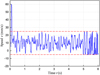 |
Fig. 24 Longitudinal moving speed of bit. |
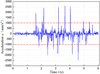 |
Fig. 25 Longitudinal moving acceleration of bit. |
The acceleration simulation data of these seven PDC cutters is shown in Figure 26. It can be seen from Figure 26 that as the drilling time increases, the acceleration of the PDC cutter at each position on the surface of the cone gradually increases. After 1 s, the acceleration value suddenly increases, and the acceleration of the seven PDC cutters reaches the maximum when approaching 1.5 s. After 1.5 s, the acceleration of each PDC tooth is in a small fluctuation, but the overall trend is stable. The reason for the acceleration fluctuation in the simulation experiment is that the cone rotates around the cone axis during the drilling process of the single-cone bit, and generates rolling rock-breaking, which in turn causes the bit to vibrate, and ultimately causes the acceleration of the PDC cutter to fluctuate. The acceleration of the 4# tooth is greater than that of the 1# tooth, which is consistent with the analysis results of Figures 12 and 14. According to the acceleration fluctuation curve after 1.5 s in Figure 26, the average curve of each PDC tooth is made, and the theoretical calculation value in Figure 14 is compared with the simulation experiment average value in Figure 26 (Tab. 4). Table 4 shows that the acceleration values of the PDC cutter obtained through the simulation experiment are all greater than the theoretical calculation values, and the fractional error between the theoretical analysis results of the acceleration of the PDC cutter and the simulation experiment results is between −0.95% and −2.24%. This shows that this paper is advisable to study the acceleration theory of the spherical single-cone PDC compound bit.
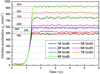 |
Fig. 26 Absolute acceleration of PDC cutters. |
Theoretical and simulated values of PDC cutter acceleration.
7 Conclusion
In this paper, the acceleration equation of the spherical single-cone PDC compound bit is established; sandstone, limestone and granite are selected respectively, and the acceleration of the spherical single-cone PDC compound bit is quantitatively analyzed and calculated; the acceleration of the single-cone bit is verified by numerical simulation experiment of rock-breaking, with the following conclusions drawn.
The bit transmission ratio i increases as the shaft inclination angle β increases, and the harder the rock formation, the larger the single-cone bit transmission ratio i; the rock formation has an influence on the acceleration of the cutting teeth, and the acceleration of the cutting teeth in the hard rock layer is higher than that in the soft rock layer.
The shaft inclination angle and the position height of the PDC teeth have a greater impact on the acceleration of the PDC teeth, and close to the top of the cone, the absolute acceleration of the cutting teeth will fluctuate sharply and cause severe wear of the cutting teeth; the greater β, the closer the absolute acceleration fluctuation position is to the top of the cone, and the smaller the fluctuation amplitude; the absolute acceleration decreases as β increases, which means that the inertial force of the drill bit is smaller; however, considering the wear of the cone bearing, the shaft inclination angle β of the single-cone bit cannot be designed too large; on the premise that the bearing life of the single-cone bit is allowed, the value of β can be approached to 70°.
The relative error between the theoretical analysis results of the acceleration of the PDC cutter and the rock-breaking simulation experiment results is between −0.95% and −2.24%. This shows that this paper is advisable to study the acceleration theory of the spherical single-cone PDC compound bit.
Acknowledgments
This research work was supported by the Key Scientific Research Fund of Xihua University (No. Z17119-0303); Research Project of Key Laboratory Machninery and Power Machinery (Xihua University), Ministry of Education.
References
- Deng R., Yang S.L., Yu K.A. (1995) Study of single spherieal roller bit, J. Southwest Pet. Univ. 17, 1, 96–100. (in Chinese). [Google Scholar]
- Langford J.W.J. (1997) One-cone bits improve efficiency of drilling small diameter holes, Pet. Eng. Int. 72, 2, 23–28. [Google Scholar]
- Witman G.B., Wilson P., Mcdonough S.D., Siracki M.A. (2008) Single cone rock bit having inserts adapted to maintain hole gage during drilling, US, 7100711. [Google Scholar]
- Moran D.P., Witman Iv G.B. (2004) One cone bit with interchangeable cutting structures, a box-end connection, and integral sensory devices, US, US6814162 B2. [Google Scholar]
- Fletcher S. (2003) Custom designed single-cone bit works for well of Albania, Oil Gas J. 101, 44–45. [Google Scholar]
- Chen L., Yang Y.X., Xie Z.L., Ren H.T., Yang L.Y. (2020) Rotating cutter single cone bit, US, US2020217141A1. [Google Scholar]
- Yu K.A., Deng R., Ma D.K. (1995) Rock disintegrating track of spherical mono-cone bit, China Pet. Mach. 23, 4, 1–7. (in Chinese). [Google Scholar]
- Hu Q., Liu Q.Y. (2006) A new disc one-cone bit, IADC/SPE 102381-MS. [Google Scholar]
- Huang H.M., Beijing Liu X.Z., Sun H. (2003) Development of slim hole single cone bit, China Pet. Mach. 31, 12, 40–41. (in Chinese). [Google Scholar]
- Huang H.M., Liu X.Z., Sun H., Zhai Y.H., Zhao H. (2003) Research and application of small size series single roller bit, China Pet. Mach. 31, 12, 40–41. (in Chinese). [Google Scholar]
- Kong C.Y., Liang Z., Zhang D.R. (2017) Failure analysis and optimum structure design of PDC cutter, Mechanika 23, 4, 567–573. https://doi.org/10.5755/j01.mech.23.4.14932. [Google Scholar]
- Miller G., Dewey C., Saylor J. (1997) Sidetracking in a single trip. Society of Petroleum Engineers. [Google Scholar]
- Yu Z.Q., Zhang J.S. (1998) Research on development prospect of single-roller bit, Fault-Block Oil Gas Field 5, 6, 48–51. [Google Scholar]
- Ma D.K. (2009) The operational mechanics of the rock bit, Petroleum Industry Press, Beijing. (in Chinese). [Google Scholar]
- Wang Z.G., Deng R., Yang G. (2007) The computer simulation model study of singular one-cone bit, Oil Field Equip. 36, 3, 26–29. (in Chinese). [Google Scholar]
- Deng R., Ao J.Z., Yang S., An M. (2014) Rock breaking simulation and cutter selection of the special single cone bit, China Pet. Mach. 12, 11–16. (in Chinese). [Google Scholar]
- Li K.R. (2018) Research and application of new type single cone bit, Mod. Manuf. Technol. Equip. 2, 41–42. (in Chinese). [Google Scholar]
- Yu K.A., Ding L.P. (2009) Study of kinematics of offset single cone bit, China Pet. Mach. 37, 1, 1–4. (in Chinese). [Google Scholar]
- Yu K.A. (2009) Study on dynamics of single cone bit, Oil Field Equip. 38, 2, 11–14. (in Chinese). [Google Scholar]
- Deng R., Yu K.A., Yang S.L. (1995) Geometry and bottom hole track of single cone bit, Oil Field Equip. 24, 5, 14–17. (in Chinese). [Google Scholar]
- Pessier R., Damschen M. (2011) Hybrid bits offer distinct advantages in selected roller-cone and PDC bit applications, SPE Drill. Complet. 26, 1, 96–103. [Google Scholar]
- Moujbani W., Aliko E., Chaabane N. (2014) Development of a PDC-tricone hybrid technology to solve drilling problems of surface holes in North Africa, in: Offshore Technology Conference-Asia. [Google Scholar]
- Miao S., Blackman M., Luo J., Luo L. (2016) Hybrid bit produces breakthrough performance in heterogeneous formations in China, in: Offshore Technology Conference Asia. [Google Scholar]
- Hurlburt M., Quintero J., Bradshaw R., Belloso A., Glass D. (2019) Combining state-of-the-art hybrid bit and positive displacement motors saves 863,670 CAD over 20 wells in Northern Alberta, Canada, in: SPE Oklahoma City Oil and Gas Symposium. [Google Scholar]
- Chowdhury A.R., Serrano R., Rodrigue W. (2019) Pilot bit and reamer matching: real-time downhole data differentiates hybrid drill bit’s suitability with concentric reamer in deepwater, Gulf of Mexico application, in: SPE/IADC International Drilling Conference and Exhibition. [Google Scholar]
- Zhang Y.H., Baker R., Burhan Y., Shi J., Chen C., Tammineni S., Durairajan B., Self J., Segal S. (2013) Innovative rolling PDC cutter increases drilling efficiency improving bit performance in challenging applications, in: SPE/IADC 163536, 5–7 March. [Google Scholar]
- Giumelli M., O’Shea P., Maliardi A., Sosnowski P., Shepherd A., Sadawarte S.S., Maurizio S. (2014) Offshore exploration program benefits from rolling PDC cutter Technology, in: Timor Sea Australia, IADC/SPE-170532-MS, 25–27 August. [Google Scholar]
- Kim E., Rostami J., Swope C. (2009) Measurement of Conical Bit Rotation, in: US Rock Mechanics Symposium & US-Canada Rock Mechanics Symposium. [Google Scholar]
- Iskandar F.F., Fanti D., Liang T.T. (2016) Innovative conical diamond element bits deliver superior performance drilling a geothermal well in the Philippines, in: OTC-26421-MS, 22–25 March. [Google Scholar]
- Pak M., Azar M., Bits S., PahI J. (2016) Conical diamond element enables PDC bit to efficiently drill chert interval at high ROP replacing turbine/impregnated BHA, in: IADC/SPE-178765-MS, 1–3 March. [Google Scholar]
- Chen L., Yang Y.X., Lin M., Ren H.T. (2013) Composite single cone bit, China Patent No. ZL 2010106143706. (in Chinese). [Google Scholar]
- Yang Y.X., Chen L., Lin M., Pei Z., Ren H.T. (2013) Scraping-wheel drill bit, US20130126246. [Google Scholar]
- Yang Y.X., Chen L., Lin M. (2015) Composite drill bit, WO2012006966 A1. [Google Scholar]
- Chen L., Yang Y.X., Liu Y., Lin M., Zhang C.L., Niu S.W. (2017) The operational theory and experimental study of scraping-wheel diamond bit, J. Pet. Sci. Eng. 156, 152–159. https://doi.org/10.1016/j.petrol.2017.04.043. [Google Scholar]
- Yang Y., Zhang C., Chen L., Liu Y. (2017) Kinematic and bottom-hole pattern analysis of a composite drill bit of cross-scraping, Proc. Inst. Mech. Eng. C 231, 17, 3104–3117. https://doi.org/10.1177/0954406216642797. [Google Scholar]
- Yang Y.X., Zhang C.L., Lin M., Chen L. (2018) Research on rock-breaking mechanism of cross-cutting PDC bit, J. Pet. Sci. Eng. 161, 657–666. https://doi.org/10.1016/j.petrol.2017.11.034. [Google Scholar]
- Yang Y.X., Kuang Y.C., Chen L., Ren H.T. (2010) Progress and development direction of rock breaking technology, in: Oil and Gas Drilling, Tenth Conference of Oil drilling Dean and Institute director, China Petroleum Institutepp. 154–160 (in Chinese). [Google Scholar]
- Yang Y.X. (2003) Research on mechanics of PDC bit rock cutting process, PhD Thesis. Southwest Petroleum University, Chengdu. (in Chinese). [Google Scholar]
- Deng R., Yang S.L., Yu K.A. (1995) Test and analysis of transmission ratio of mono-cone bits, China Pet. Mach. 23, 6, 14–17. (in Chinese). [Google Scholar]
- Wu K.S., Ma D.K. (2001) Particularity and main research direction of roller cone bit plain bearing, China Pet. Mach. 29, 004, 52–54. (in Chinese). [Google Scholar]
- Wang G.R., Zheng J.W., Kang Q.J. (2006) Failure analysis of rock bit journal bearings, Lubr. Eng. 10, 22–24. [Google Scholar]
- Zhu X.H., Yi Q.J. (2018) Research and application of reaming subsidence control in horizontal directional drilling, Tunn. Undergr. Space Technol. 75, 1–10. (in Chinese). [Google Scholar]
- Zhang M., Wang F., Yang Q. (2013) Statistical damage constitutive model for rocks based on triaxial compression tests, Chinese J. Geotech. Eng. 35, 11, 1965–1971. [Google Scholar]
- Ouyang Y.P., Yang Q. (2016) Numerical simulation of rock cutting in 3D with SPH method and estimation of cutting force, J Shanghai Jiaotong Univ. 50, 1, 84–90. (in Chinese). [Google Scholar]
- Jaime M.C., Zhou Y., Lin J.S., Gamwo I.K. (2015) Finite element modeling of rock cutting and its fragmentation process, Int. J. Rock Mech. Min. Sci. 80, 137–146. [Google Scholar]
All Tables
All Figures
|
Fig. 1 Failed single-cone bit (a) worn cutting teeth (b) broken cutting teeth. |
| In the text | |
|
Fig. 2 Bottom hole pattern of single-cone bit. |
| In the text | |
|
Fig. 3 Spherical single-cone PDC compound bit. |
| In the text | |
|
Fig. 4 The motion of spherical single-cone PDC compound bit. |
| In the text | |
|
Fig. 5 Cylindrical coordinate system for bit. |
| In the text | |
|
Fig. 6 Geometry of spherical single-cone PDC compound bit. |
| In the text | |
|
Fig. 7 Change of transmission ratio at shaft inclination angle. |
| In the text | |
|
Fig. 8 Effect of front inclination angle on acceleration. |
| In the text | |
|
Fig. 9 Effect of PDC cutter radius on acceleration. |
| In the text | |
|
Fig. 10 Effect of lateral rotation angle on acceleration. |
| In the text | |
|
Fig. 11 Effect of shaft inclination angle on acceleration. |
| In the text | |
|
Fig. 12 Effect of PDC cutter position on acceleration. |
| In the text | |
|
Fig. 13 Relationship between the absolute acceleration and hC (sandstone). |
| In the text | |
|
Fig. 14 Relationship between the absolute acceleration and hC (limestone). |
| In the text | |
|
Fig. 15 Relationship between the absolute acceleration and hC (granite). |
| In the text | |
|
Fig. 16 Change of radial acceleration along with hC and β. |
| In the text | |
|
Fig. 17 Change of tangential acceleration along with hC and β. |
| In the text | |
|
Fig. 18 Change of longitudinal acceleration along with hC and β. |
| In the text | |
|
Fig. 19 Change of absolute acceleration along with hC and β. |
| In the text | |
|
Fig. 20 Finite element model of the drill bit-rock system (a) Overall model, (b) Rock model. |
| In the text | |
|
Fig. 21 Boundary setting of rock-breaking simulation. |
| In the text | |
|
Fig. 22 Number of cutters. |
| In the text | |
|
Fig. 23 Equivalent plastic strain in rock-breaking process. |
| In the text | |
|
Fig. 24 Longitudinal moving speed of bit. |
| In the text | |
|
Fig. 25 Longitudinal moving acceleration of bit. |
| In the text | |
|
Fig. 26 Absolute acceleration of PDC cutters. |
| In the text | |